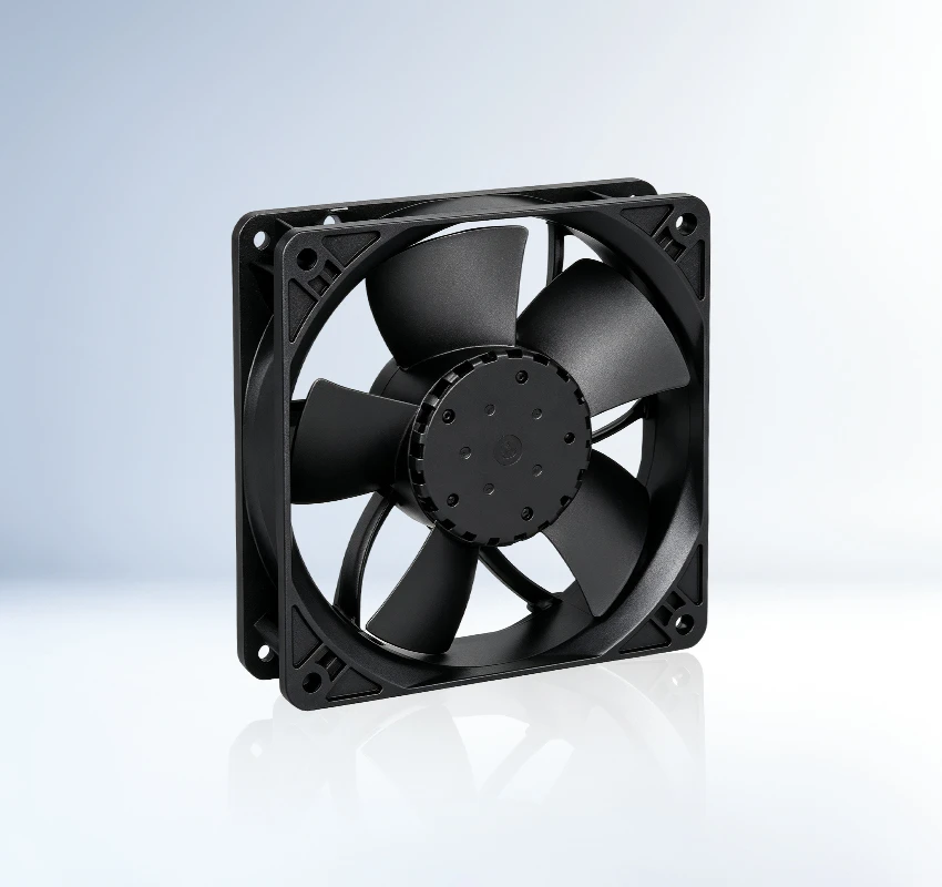
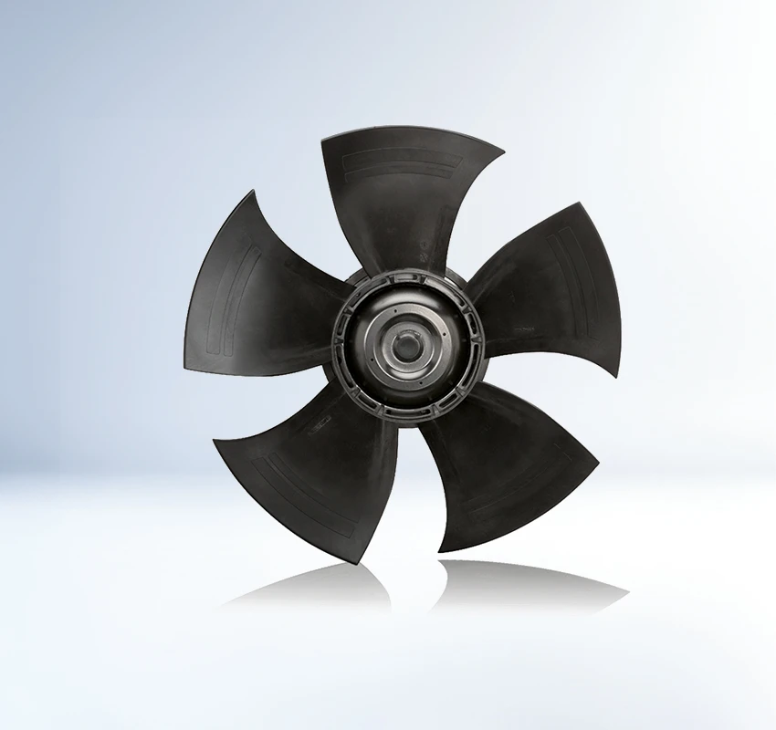
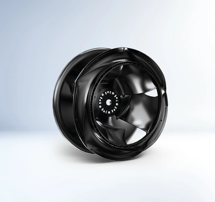
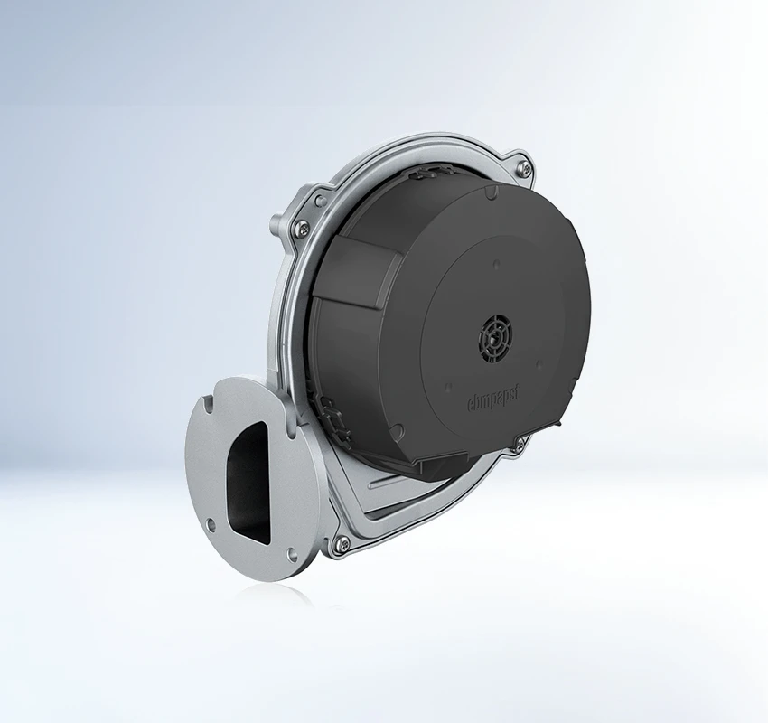
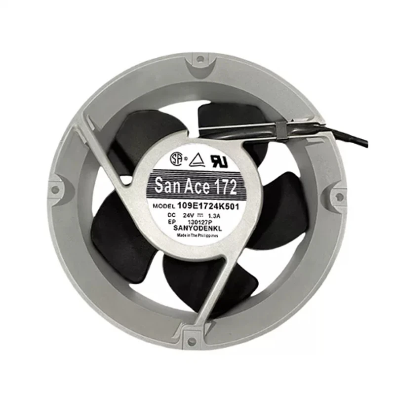
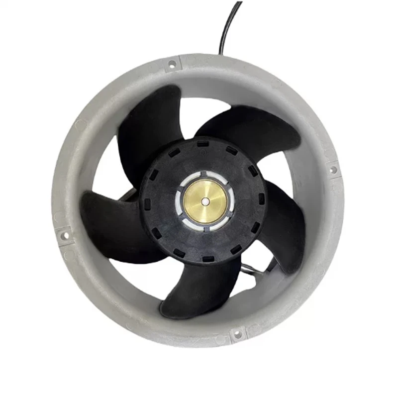
Within servers, UPS systems, and telecom equipment, 109E1724K501 provides a 172φ × 51 mm, 24 VDC DC axial fan configuration. High airflow is highlighted together with a high-static-pressure design. The 172φ × 51 mm format is the primary stated selection detail. Check control interface planning sound level. Focus: control interface planning.
| Rated Voltage(V) | 24 |
|---|---|
| Size(mm) | 172φ*51 |
109E1724K501 is intended for dependable forced-air cooling in servers, storage systems and ICT equipment. This SANYO DENKI DC axial fan fits equipment designs where thermal stability affects service continuity.
Engineers should review the model-specific fan curve against filters, grilles and enclosure resistance to confirm the required operating point. For design approval, verify airflow direction, connector details and available control signals. Prototype testing should include the final vents, guards and component loading.
Review airflow direction before design release. The review links cooling performance to the approved BOM. Confirm the final fan curve in the assembled equipment. Preserve clear inlet and outlet space during installation.
For server chassis and computing nodes, 109E1724K501 provides a dedicated forced-air cooling path. These systems need continuous heat removal because compact layouts and rising power density restrict natural convection. This helps maintain dependable equipment operation.
SANYO DENKI 109E1724K501 serves storage arrays and data appliances that operate with sustained internal heat. These systems need continuous heat removal because compact layouts and rising power density restrict natural convection. This helps maintain dependable equipment operation.
109E1724K501 is suitable for network and other ICT hardware. Directed airflow carries component heat toward the equipment exhaust and helps maintain a controlled internal temperature. This helps maintain dependable equipment operation. Selection should follow the approved full model code.
PWM or sensor functions depend on the exact suffix. Confirm the control lead and interface in the applicable Sanyo Denki datasheet.
Availability and lead time can change. Confirm the exact suffix, quantity, and delivery date with the supplier before ordering.
The worksheet lists 24 VDC. Check polarity or AC frequency and the wiring diagram before commissioning.
Verify supply, connector, obstructions, impeller movement, and alarm or protection status using the model-specific troubleshooting data.
Confirm full suffix, voltage, connector, control signal, bearing, IP rating, certifications, stock, and required delivery date.

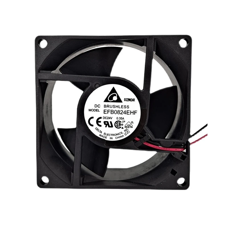
EFB0824EHF brings a 32 mm-deep axial format to industrial electronics cooling. This 24VDC fan measures 80 mm square and lists 5200 rpm operation, with 122.4 Pa maximum static pressure and 5.52 W input.
查看更多
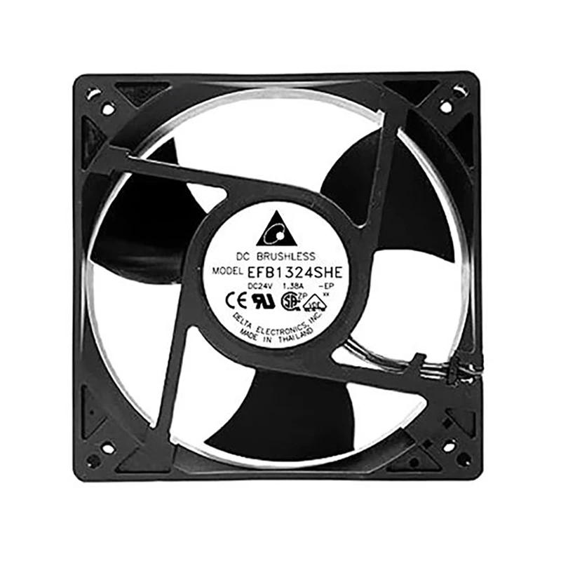
For industrial equipment, EFB1324SHE uses a 127 x 127 x 38 mm axial package rather than the common 120 mm format. The 24VDC fan lists 4600 rpm operation and 339.8 m3/h maximum airflow with 18 W input.
查看更多
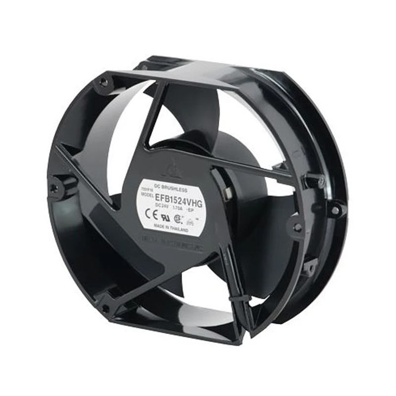
EFB1524VHG offers a 4000 rpm axial fan option for 24VDC industrial cooling. Compared with the listed SHG entry, its 23.28 W input and 507.6 m3/h maximum airflow define a different operating point for equipment selection.
查看更多
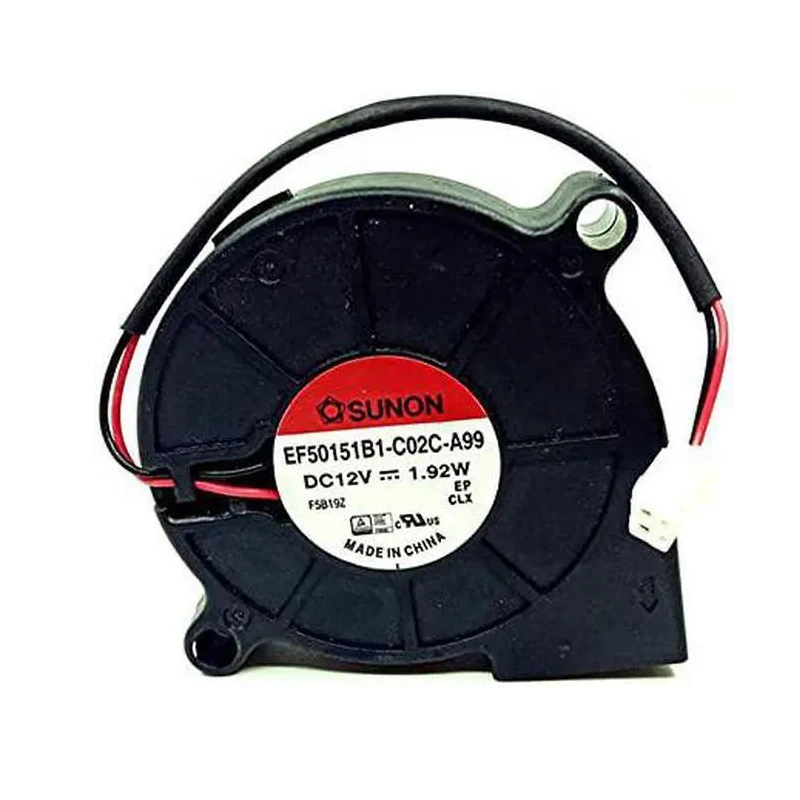
EF50151B1-C02C-A99 addresses telecom cabinets, base stations, and network equipment through a 12 VDC DC blower platform measuring 50 × 50 × 15 mm. Its 7.6 m³/h airflow rating suits the stated equipment-cooling role. Base airflow-path design on the stated product configuration. Obtain the applicable curve before final duty-point approval.
查看更多
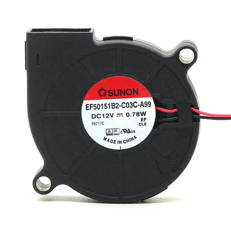
SUNON EF50151B2-C03C-A99 combines a 50 × 50 × 15 mm DC blower platform with a 12 VDC rating for telecom cabinets, base stations, and network equipment. Its 5.9 m³/h airflow rating suits the stated equipment-cooling role. During airflow-path design, compare the model's system interface. Obtain the applicable curve before final duty-point approval.
查看更多
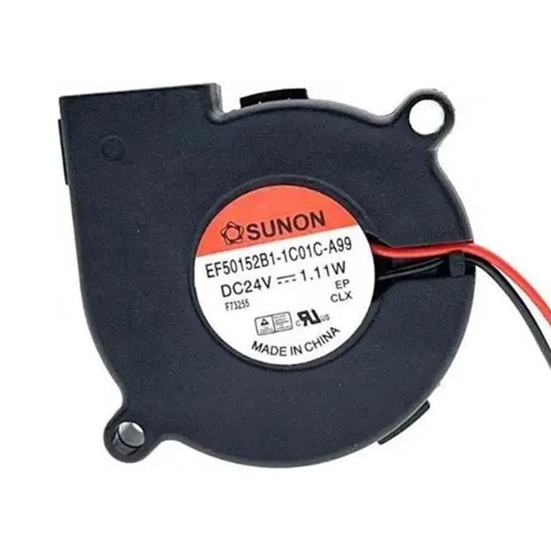
Within telecom cabinets, base stations, and network equipment, EF50152B1-1C01U-A99 provides a 50 × 50 × 15 mm, 24 VDC DC blower configuration. A listed input of 1.11 W is the model's notable electrical characteristic. Treat the dimensional envelope as a primary input to mounting verification. Validate mounting and wiring from the model drawing.
查看更多